

Unfortunately, when we powered it up, at the hackspace, nothing came on.
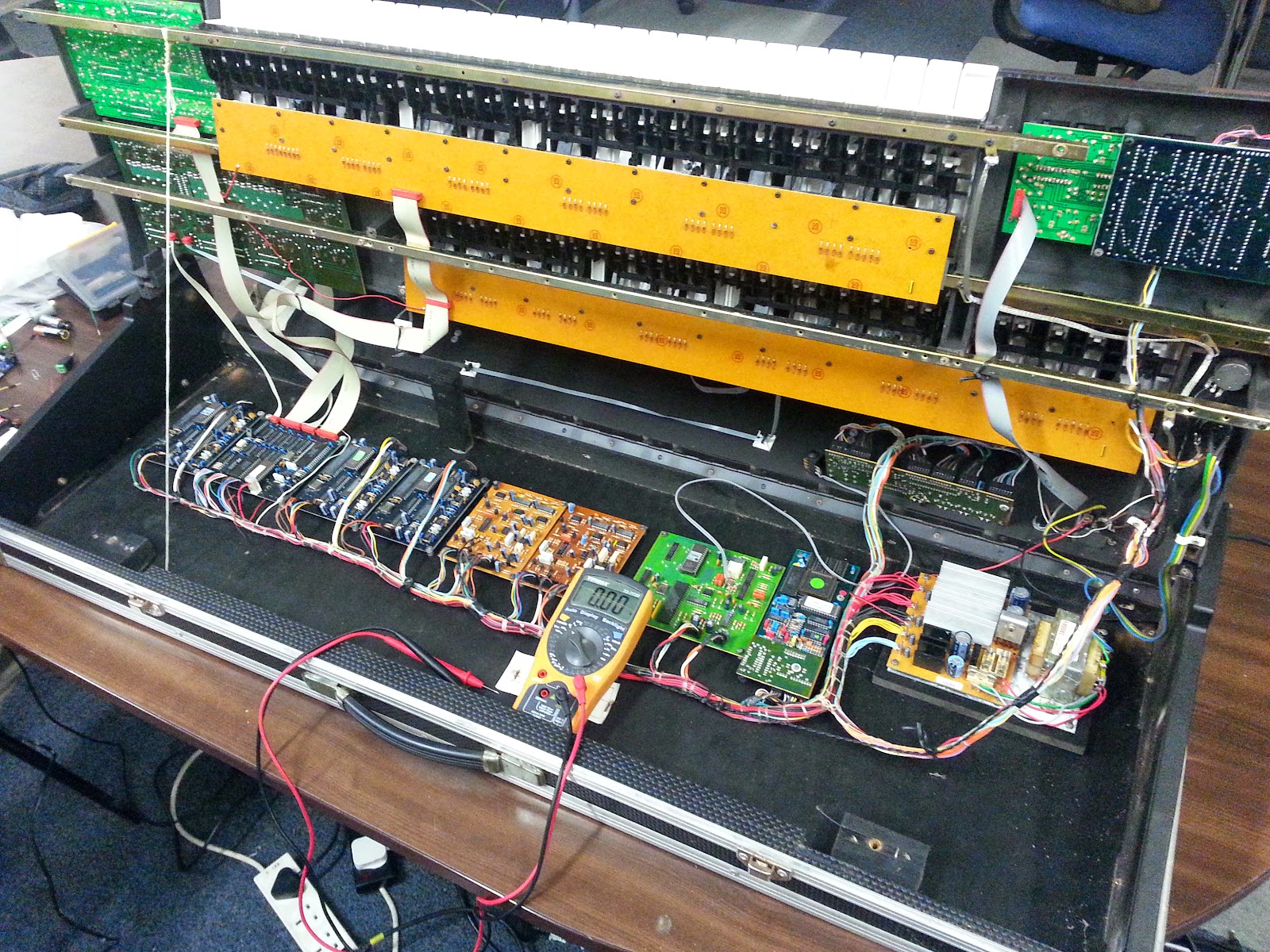
We checked for continuity across the power in and power out distribution board, and everything seemed to be in order. We even went so far as to put the multimeter on the exposed wires while it was hooked up to power and switched on (not something we're ever happy doing - messing about with low voltage, 5v logic signals is all well and good, but playing around with exposed wires with 240V live voltage from the mains floating around, and suddenly you're not just messing about.)
Opening up the keyboard from it's inbuilt flight-case enclosure didn't really offer much enlightenment.
Suddenly, the keyboard came to life. All the buttons flashed, the BMP indicator reported a steady 60bpm, and pressing the keys on the lower deck produced some pleasing (actually, not-so-pleasing-rather-crappy-sounding) 80's style synth drum sounds - and, of course, the inevitable handclap.
Then it all went dead again.
Then the lights all came on but the keyboard didn't respond.
This went on for about an hour and a half. There was obviously a loose connection or two, somewhere within the unit. But where?! Another hour or so of poking about, and we decided on some drastic action.
We got the keyboard just because of the nice double-decked keys - everything else was a bonus. So if everything else around it didn't work reliably, there was only one thing to do: get rid of it!
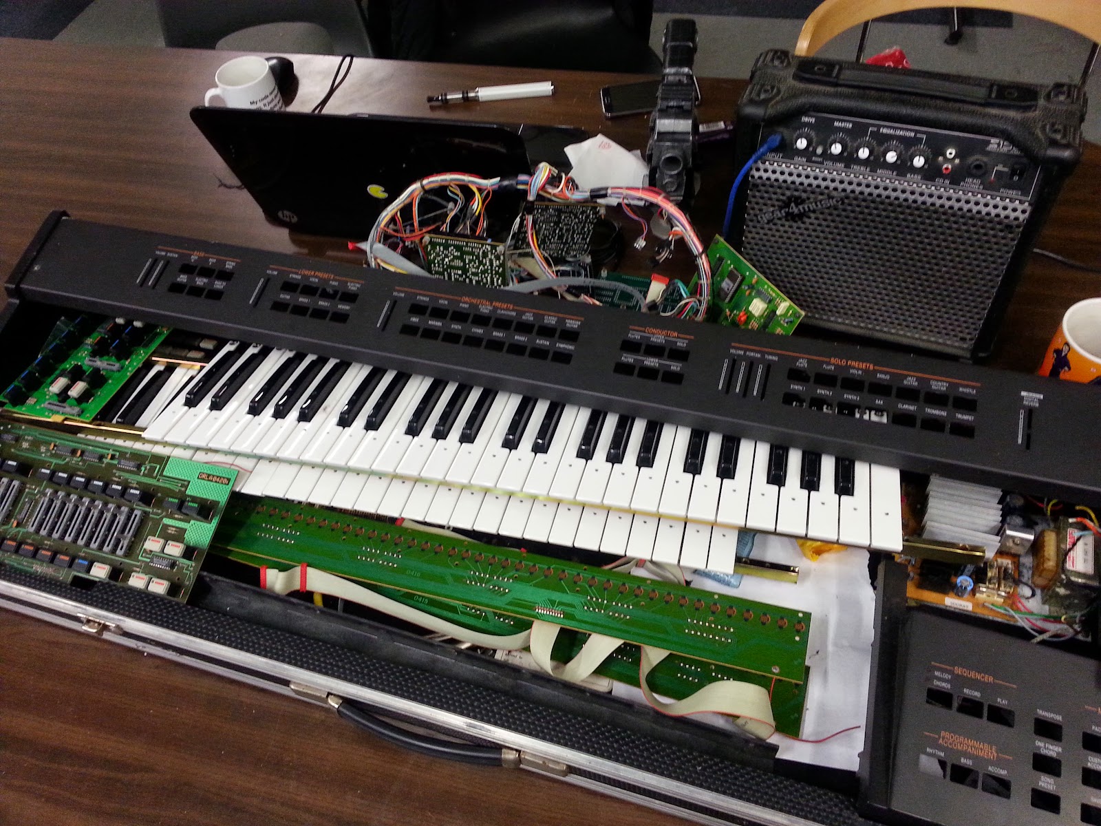
The first thing to do was remove the keys and keep these somewhere safe.
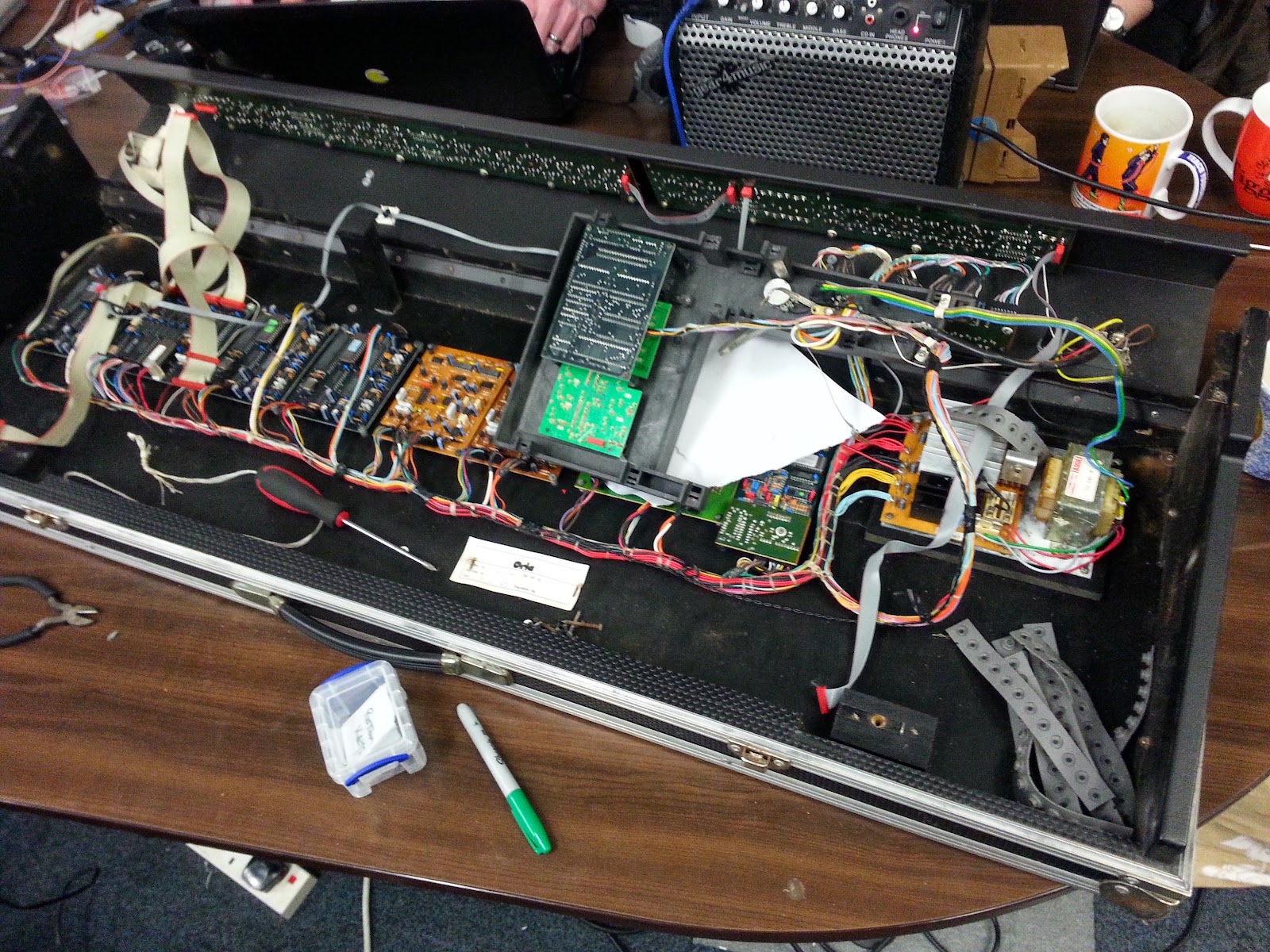
Next we had to gut the inside of the keyboard. Although the tech inside was fascinating from a history point of view, most of it was pretty worthless now. Who needs a separate wave-table for each sound type on a piano any more? It was pretty archaic.
And not just old-fashioned. A lot of the joints were corroded and rusty inside. There could be any number of faults with this old thing. Originally the idea was to keep the keyboard working in it's original state and simply add LEDs onto each of the keys on the upper deck. It soon became apparent that what we needed to do was build an entirely new MIDI device.
To turn a busted keyboard into a MIDI device that could display which notes to play would not only mean accepting and understanding incoming data from the MIDI port, but also being able to detect key presses and generate outgoing MIDI data to send to a sequencer or PC or similar.
Luckily, the method of detecting key presses on this particular keyboard was pretty simple.

Dating from some time before the "date last checked" sticker inside, which said June 1989, this keyboard didn't have such niceties as velocity detect on the keys - a keypress is either on or off, there's no detecting how hard each key is struck; this is a purely digital device. And that's just fine with us!
Each keyboard has 4 full octaves. From previous posts, we know that this is 4 lots of 12 intervals - or 48 keys per board. To read these keypresses, underneath each key is a circuit which groups the keys into bunches of eight. Each bunch of eight keys has a common connection on one side, with six lots of 8 input signals running off to a pin-header connector.
For all the world (and thanks to the presence of a diode on every single input key) like the system used multi-plexing to read the keyboard in groups of eight notes at a time. Even if that's not how it did work, we can reuse the existing circuitry to make our device work like this.
The general idea is that of the six common connections, only one group of eight are pulled to ground at any one time. The other side of the eight input pads run to input pins on a microcontroller, each of which is pulled high though a weak internal pull-up resistor.
Where a key is pressed, the input signal would appear low. Where a key is released, the input signal would be high. Once a bank of eight notes has been read, the common connector for those eight pads goes high, and the common connector on the next set of eight pads goes low. Now the same input pins can be used to interrogate the next bunch of eight notes along. Any input pin that is now low indicates a different key that has been pressed.
Although one input pin is potentially connected to up to six different pads, by knowing which bank of eight keys has been pulled low before querying the pads, we can work out which of the 48 keys are pressed and which are released, despite only using 6+8 = 14 i/o pins.
As time was tight, we'd already wasted a good few hours, and Steve was getting hungry, we set about preparing for the original part of the project - adding LEDs to the keys.

A 3mm hole was drilled into the surface of each white and each black note on the keyboard. Where possible we tried to keep them as close to the centre as possible. The keys were unusually brittle and we had to take care, drilling very slowly through each piece of moulded plastic.

We tested the hole for fitting by placing a 3mm LED on the underside. When it comes to it, we're going to have to dismantle each section and hot-glue each LED in place under each key, and common up the appropriate LED leads, to connect them to our MAX7219 controller.
At the end of the night, our double-layered electronic keyboard didn't look much like the beautiful looking thing we brought in just a few short hours earlier.
Hopefully it won't be too long before we can start re-assembling the keyboard and get on our way towards making it somewhere near playable again!
No comments:
Post a Comment